A transformer is a device that transfers electrical energy from one circuit to another through inductively coupled electrical conductors. A changing current in the first circuit (the primary) creates a changing magnetic field. This changing magnetic field induces a changing voltage in the second circuit (the secondary). This effect is called mutual induction.
If a load is connected to the secondary circuit, electric charge will flow in the secondary winding of the transformer and transfer energy from the primary circuit to the load connected in the secondary circuit.
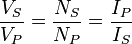
The secondary induced voltage (VS), of an ideal transformer, is scaled from the primary voltage (VP) by a factor equal to the ratio of the number of turns of wire in their respective windings:

By appropriate selection of the numbers of turns, a transformer thus allows an alternating voltage to be stepped up — by making NS more than NP — or stepped down, by making it less.
Transformers are some of the most efficient electrical 'machines',[1] with some large units able to transfer 99.75% of their input power to their output.[2] Transformers come in a range of sizes from a thumbnail-sized coupling transformer hidden inside a stage microphone to huge units weighing hundreds of tons used to interconnect portions of national power grids. All operate with the same basic principles, although the range of designs is wide.
The transformer principle was demonstrated in 1831 by Michael Faraday, although he used it only to demonstrate the principle of electromagnetic induction and did not foresee its practical uses. The first widely used transformer was the induction coil, invented by Irish clergyman Nicholas Callan in 1836.[3] He was one of the first to understand the principle that the more turns a transformer winding has, the larger EMF it produces. Induction coils evolved from scientists' efforts to get higher voltages from batteries. They were powered not by AC, but DC from batteries which was interrupted by a vibrating 'breaker' mechanism. Between the 1830s and the 1870s efforts to build better induction coils, mostly by trial and error, slowly revealed the basic principles of transformer operation. Efficient designs would not appear until the 1880s,[4] but within less than a decade, the transformer was instrumental during the "War of Currents" in seeing alternating current systems triumph over their direct current counterparts, a position in which they have remained dominant.[4]
Russian engineer Pavel Yablochkov in 1876 invented a lighting system based on a set of induction coils, where primary windings were connected to a source of alternating current and secondary windings could be connected to several "electric candles". The patent claimed the system could "provide separate supply to several lighting fixtures with different luminous intensities from a single source of electric power". Evidently, the induction coil in this system operated as a transformer.
Lucien Gaulard and John Dixon Gibbs, who first exhibited a device with an open iron core called a 'secondary generator' in London in 1882 and then sold the idea to American company Westinghouse.[5] They also exhibited the invention in Turin in 1884, where it was adopted for an electric lighting system.
Hungarian engineers Zipernowsky, Bláthy and Déri from the Ganz company in Budapest created the efficient "ZBD" closed-core model in 1885 based on the design by Gaulard and Gibbs.[6]
William Stanley, an engineer for Westinghouse, built the first commercial device in 1885 after George Westinghouse had bought Gaulard and Gibbs' patents. The core was made from interlocking E-shaped iron plates. This design was first used commercially in 1886.[4] Their patent application made the first use of the word "transformer".[5] Russian engineer Mikhail Dolivo-Dobrovolsky developed the first three-phase transformer in 1889. In 1891 Nikola Tesla invented the Tesla coil, an air-cored, dual-tuned resonant transformer for generating very high voltages at high frequency. Audio frequency transformers (at the time called repeating coils) were used by the earliest experimenters in the development of the telephone.
While new technologies have made transformers in some electronics applications obsolete, transformers are still found in many electronic devices. Transformers are essential for high voltage power transmission, which makes long distance transmission economically practical.
Basic principles
The transformer is based on two principles: firstly, that an electric current can produce a magnetic field (electromagnetism) and secondly that a changing magnetic field within a coil of wire induces a voltage across the ends of the coil (electromagnetic induction). By changing the current in the primary coil, it changes the strength of its magnetic field; since the changing magnetic field extends into the secondary coil, a voltage is induced across the secondary.
A simplified transformer design is shown to the left. A current passing through the primary coil creates a magnetic field. The primary and secondary coils are wrapped around a core of very high magnetic permeability, such as iron; this ensures that most of the magnetic field lines produced by the primary current are within the iron and pass through the secondary coil as well as the primary coil.
Induction law
The voltage induced across the secondary coil may be calculated from Faraday's law of induction, which states that:
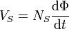
where VS is the instantaneous voltage, NS is the number of turns in the secondary coil and Φ equals the magnetic flux through one turn of the coil. If the turns of the coil are oriented perpendicular to the magnetic field lines, the flux is the product of the magnetic field strength B and the area A through which it cuts. The area is constant, being equal to the cross-sectional area of the transformer core, whereas the magnetic field varies with time according to the excitation of the primary. Since the same magnetic flux passes through both the primary and secondary coils in an ideal transformer,[1] the instantaneous voltage across the primary winding equals

Taking the ratio of the two equations for VS and VP gives the basic equation[7] for stepping up or stepping down the voltage
Ideal power equation
If the secondary coil is attached to a load that allows current to flow, electrical power is transmitted from the primary circuit to the secondary circuit. Ideally, the transformer is perfectly efficient; all the incoming energy is transformed from the primary circuit to the magnetic field and into the secondary circuit. If this condition is met, the incoming electric power must equal the outgoing power.
- Pincoming = IPVP = Poutgoing = ISVS
giving the ideal transformer equation
If the voltage is increased (stepped up) (VS > VP), then the current is decreased (stepped down) (IS < IP) by the same factor. Transformers are efficient so this formula is a reasonable approximation.
The impedance in one circuit is transformed by the square of the turns ratio.[1] For example, if an impedance ZS is attached across the terminals of the secondary coil, it appears to the primary circuit to have an impedance of  . This relationship is reciprocal, so that the impedance ZP of the primary circuit appears to the secondary to be
  .
.
Detailed operation
The simplified description above neglects several practical factors, in particular the primary current required to establish a magnetic field in the core, and the contribution to the field due to current in the secondary circuit.
Models of an ideal transformer typically assume a core of negligible reluctance with two windings of zero resistance.[8] When a voltage is applied to the primary winding, a small current flows, driving flux around the magnetic circuit of the core.[8]. The current required to create the flux is termed the magnetizing current; since the ideal core has been assumed to have near-zero reluctance, the magnetizing current is negligible, although still required to create the magnetic field.
The changing magnetic field induces an electromotive force (EMF) across each winding.[9] Since the ideal windings have no impedance, they have no associated voltage drop, and so the voltages VP and VS measured at the terminals of the transformer, are equal to the corresponding EMFs. The primary EMF, acting as it does in opposition to the primary voltage, is sometimes termed the "back EMF".[10] This is due to Lenz's law which states that the induction of EMF would always be such that it will oppose development of any such change in magnetic field.
Equivalent circuit
- Refer to the diagram below
The physical limitations of the practical transformer may be brought together as an equivalent circuit model (shown below) built around an ideal lossless transformer.[22] Power loss in the windings is current-dependent and is represented as in-series resistances RP and RS. Flux leakage results in a fraction of the applied voltage dropped without contributing to the mutual coupling, and thus can be modeled as reactances of each leakage inductance XP and XS in series with the perfectly-coupled region.
Iron losses are caused mostly by hysteresis and eddy current effects in the core, and are proportional to the square of the core flux for operation at a given frequency.[23] Since the core flux is proportional to the applied voltage, the iron loss can be represented by a resistance RC in parallel with the ideal transformer.
A core with finite permeability requires a magnetizing current IM to maintain the mutual flux in the core. The magnetizing current is in phase with the flux; saturation effects cause the relationship between the two to be non-linear, but for simplicity this effect tends to be ignored in most circuit equivalents.[23] With a sinusoidal supply, the core flux lags the induced EMF by 90° and this effect can be modeled as a magnetizing reactance (reactance of an effective inductance) XM in parallel with the core loss component. RC and XM are sometimes together termed the magnetizing branch of the model. If the secondary winding is made open-circuit, the current I0 taken by the magnetizing branch represents the transformer's no-load current.[22]
The secondary impedance RS and XS is frequently moved (or "referred") to the primary side after multiplying the components by the impedance scaling factor  .
.

The resulting model is sometimes termed the "exact equivalent circuit", though it retains a number of approximations, such as an assumption of linearity.[22] Analysis may be simplified by moving the magnetizing branch to the left of the primary impedance, an implicit assumption that the magnetizing current is low, and then summing primary and referred secondary impedances, resulting in so-called equivalent impedance.
The parameters of equivalent circuit of a transformer can be calculated from the results of two transformer tests: open-circuit test and short-circuit test.
Types
- For more details on this topic, see Transformer types.
A wide variety of transformer designs are used for different applications, though they share several common features. Important common transformer types include:
Autotransformer
An autotransformer has only a single winding with two end terminals, plus a third at an intermediate tap point. The primary voltage is applied across two of the terminals, and the secondary voltage taken from one of these and the third terminal. The primary and secondary circuits therefore have a number of windings turns in common.[24] Since the volts-per-turn is the same in both windings, each develops a voltage in proportion to its number of turns. An adjustable autotransformer is made by exposing part of the winding coils and making the secondary connection through a sliding brush, giving a variable turns ratio. [25]
Polyphase transformers
- For more details on this topic, see Three-phase electric power.
For three-phase supplies, a bank of three individual single-phase transformers can be used, or all three phases can be incorporated as a single three-phase transformer. In this case, the magnetic circuits are connected together, the core thus containing a three-phase flow of flux.[26] A number of winding configurations are possible, giving rise to different attributes and phase shifts.[27] One particular polyphase configuration is the zigzag transformer, used for grounding and in the suppression of harmonic currents.[28]
[edit] Leakage transformers

A leakage transformer, also called a stray-field transformer, has a significantly higher leakage inductance than other transformers, sometimes increased by a magnetic bypass or shunt in its core between primary and secondary, which is sometimes adjustable with a set screw. This provides a transformer with an inherent current limitation due to the loose coupling between its primary and the secondary windings. The output and input currents are low enough to prevent thermal overload under all load conditions – even if the secondary is shorted.
Leakage transformers are used for arc welding and high voltage discharge lamps (neon lamps and cold cathode fluorescent lamps, which are series-connected up to 7.5 kV AC). It acts then both as a voltage transformer and as a magnetic ballast.
Other applications are short-circuit-proof extra-low voltage transformers for toys or doorbell installations.
Resonant transformers
A resonant transformer is a kind of the leakage transformer. It uses the leakage inductance of its secondary windings in combination with external capacitors, to create one or more resonant circuits. Resonant transformers such as the Tesla coil can generate very high voltages, and are able to provide much higher current than electrostatic high-voltage generation machines such as the Van de Graaff generator.[29] One of the application of the resonant transformer is for the CCFL inverter. Another application of the resonant transformer is to couple between stages of a superheterodyne receiver, where the selectivity of the receiver is provided by tuned transformers in the intermediate-frequency amplifiers.[30]
Instrument transformers

A current transformer is a measurement device designed to provide a current in its secondary coil proportional to the current flowing in its primary. Current transformers are commonly used in metering and protective relaying, where they facilitate the safe measurement of large currents. The current transformer isolates measurement and control circuitry from the high voltages typically present on the circuit being measured.[31]
Voltage transformers (VTs)--also referred to as potential transformers (PTs)--are used for metering and protection in high-voltage circuits. They are designed to present negligible load to the supply being measured and to have a precise voltage ratio to accurately step down high voltages so that metering and protective relay equipment can be operated at a lower potential.[32]
Classification
Transformers can be classified in different ways:
- By power level: from a fraction of a volt-ampere (VA) to over a thousand MVA;
- By frequency range: power-, audio-, or radio frequency;
- By voltage class: from a few volts to hundreds of kilovolts;
- By cooling type: air cooled, oil filled, fan cooled, or water cooled;
- By application function: such as power supply, impedance matching, output voltage and current stabilizer, or circuit isolation;
- By end purpose: distribution, rectifier, arc furnace, amplifier output;
- By winding turns ratio: step-up, step-down, isolating (near equal ratio), variable.
Construction
Cores
Laminated steel cores
Transformers for use at power or audio frequencies typically have cores made of high permeability silicon steel.[33] The steel has a permeability many times that of free space, and the core thus serves to greatly reduce the magnetizing current, and confine the flux to a path which closely couples the windings.[34] Early transformer developers soon realized that cores constructed from solid iron resulted in prohibitive eddy-current losses, and their designs mitigated this effect with cores consisting of bundles of insulated iron wires.[5] Later designs constructed the core by stacking layers of thin steel laminations, a principle that has remained in use. Each lamination is insulated from its neighbors by a thin non-conducting layer of insulation.[26] The universal transformer equation indicates a minimum cross-sectional area for the core to avoid saturation.
The effect of laminations is to confine eddy currents to highly elliptical paths that enclose little flux, and so reduce their magnitude. Thinner laminations reduce losses,[33] but are more laborious and expensive to construct.[35] Thin laminations are generally used on high frequency transformers, with some types of very thin steel laminations able to operate up to 10 kHz.

One common design of laminated core is made from interleaved stacks of E-shaped steel sheets capped with I-shaped pieces, leading to its name of "E-I transformer".[35] Such a design tends to exhibit more losses, but is very economical to manufacture. The cut-core or C-core type is made by winding a steel strip around a rectangular form and then bonding the layers together. It is then cut in two, forming two C shapes, and the core assembled by binding the two C halves together with a steel strap.[35] They have the advantage that the flux is always oriented parallel to the metal grains, reducing reluctance.
A steel core's remanence means that it retains a static magnetic field when power is removed. When power is then reapplied, the residual field will cause a high inrush current until the effect of the remaining magnetism is reduced, usually after a few cycles of the applied alternating current.[36] Overcurrent protection devices such as fuses must be selected to allow this harmless inrush to pass. On transformers connected to long, overhead power transmission lines, induced currents due to geomagnetic disturbances during solar storms can cause saturation of the core and operation of transformer protection devices.[37]
Distribution transformers can achieve low no-load losses by using cores made with low-loss high-permeability silicon steel or amorphous (non-crystalline) metal alloy. The higher initial cost of the core material is offset over the life of the transformer by its lower losses at light load.[38]
Solid cores
Powdered iron cores are used in circuits (such as switch-mode power supplies) that operate above main frequencies and up to a few tens of kilohertz. These materials combine high magnetic permeability with high bulk electrical resistivity. For frequencies extending beyond the VHF band, cores made from non-conductive magnetic ceramic materials called ferrites are common.[35] Some radio-frequency transformers also have movable cores (sometimes called 'slugs') which allow adjustment of the coupling coefficient (and bandwidth) of tuned radio-frequency circuits.
Toroidal cores
Toroidal transformers are built around a ring-shaped core, which, depending on operating frequency, is made from a long strip of silicon steel or permalloy wound into a coil, powdered iron, or ferrite.[39] A strip construction ensures that the grain boundaries are optimally aligned, improving the transformer's efficiency by reducing the core's reluctance. The closed ring shape eliminates air gaps inherent in the construction of an E-I core.[40] The cross-section of the ring is usually square or rectangular, but more expensive cores with circular cross-sections are also available. The primary and secondary coils are often wound concentrically to cover the entire surface of the core. This minimizes the length of wire needed, and also provides screening to minimize the core's magnetic field from generating electromagnetic interference.
Toroidal transformers are more efficient than the cheaper laminated E-I types for a similar power level. Other advantages compared to E-I types, include smaller size (about half), lower weight (about half), less mechanical hum (making them superior in audio amplifiers), lower exterior magnetic field (about one tenth), low off-load losses (making them more efficient in standby circuits), single-bolt mounting, and greater choice of shapes. The main disadvantages are higher cost and limited rating.
Ferrite toroidal cores are used at higher frequencies, typically between a few tens of kilohertz to a megahertz, to reduce losses, physical size, and weight of switch-mode power supplies. A drawback of toroidal transformer construction is the higher cost of windings. As a consequence, toroidal transformers are uncommon above ratings of a few kVA. Small distribution transformers may achieve some of the benefits of a toroidal core by splitting it and forcing it open, then inserting a bobbin containing primary and secondary windings.
[edit] Air cores
A physical core is not an absolute requisite and a functioning transformer can be produced simply by placing the windings in close proximity to each other, an arrangement termed an "air-core" transformer. The air which comprises the magnetic circuit is essentially lossless, and so an air-core transformer eliminates loss due to hysteresis in the core material.[10] The leakage inductance is inevitably high, resulting in very poor regulation, and so such designs are unsuitable for use in power distribution.[10] They have however very high bandwidth, and are frequently employed in radio-frequency applications,[41] for which a satisfactory coupling coefficient is maintained by carefully overlapping the primary and secondary windings.
Windings
The conducting material used for the windings depends upon the application, but in all cases the individual turns must be electrically insulated from each other to ensure that the current travels throughout every turn.[13] For small power and signal transformers, in which currents are low and the potential difference between adjacent turns is small, the coils are often wound from enamelled magnet wire, such as Formvar wire. Larger power transformers operating at high voltages may be wound with copper rectangular strip conductors insulated by oil-impregnated paper and blocks of pressboard.[42]
High-frequency transformers operating in the tens to hundreds of kilohertz often have windings made of braided litz wire to minimize the skin-effect and proximity effect losses.[13] Large power transformers use multiple-stranded conductors as well, since even at low power frequencies non-uniform distribution of current would otherwise exist in high-current windings.[42] Each strand is individually insulated, and the strands are arranged so that at certain points in the winding, or throughout the whole winding, each portion occupies different relative positions in the complete conductor. The transposition equalizes the current flowing in each strand of the conductor, and reduces eddy current losses in the winding itself. The stranded conductor is also more flexible than a solid conductor of similar size, aiding manufacture.[42]
For signal transformers, the windings may be arranged in a way to minimize leakage inductance and stray capacitance to improve high-frequency response. This can be done by splitting up each coil into sections, and those sections placed in layers between the sections of the other winding. This is known as a stacked type or interleaved winding.
Both the primary and secondary windings on power transformers may have external connections, called taps, to intermediate points on the winding to allow selection of the voltage ratio. The taps may be connected to an automatic on-load tap changer for voltage regulation of distribution circuits. Audio-frequency transformers, used for the distribution of audio to public address loudspeakers, have taps to allow adjustment of impedance to each speaker. A center-tapped transformer is often used in the output stage of an audio power amplifier in a push-pull circuit. Modulation transformers in AM transmitters are very similar.
Certain transformers have the windings protected by epoxy resin. By impregnating the transformer with epoxy under a vacuum, one can replace air spaces within the windings with epoxy, thus sealing the windings and helping to prevent the possible formation of corona and absorption of dirt or water. This produces transformers more suited to damp or dirty environments, but at increased manufacturing cost.[43]
Coolant
High temperatures will damage the winding insulation. [44] Small transformers do not generate significant heat and are cooled by air circulation and radiation of heat. Power transformers rated up to several hundred kVA can be adequately cooled by natural convective air-cooling, sometimes assisted by fans.[45] In larger transformers, part of the design problem is removal of heat. Some power transformers are immersed in transformer oil that both cools and insulates the windings.[46] The oil is a highly refined mineral oil that remains stable at transformer operating temperature. Indoor liquid-filled transformers must use a non-flammable liquid, or must be located in fire resistant rooms.[2] Air-cooled dry transformers are preferred for indoor applications even at capacity ratings where oil-cooled construction would be more economical, because their cost is offset by the reduced building construction cost.
The oil-filled tank often has radiators through which the oil circulates by natural convection; some large transformers employ forced circulation of the oil by electric pumps, aided by external fans or water-cooled heat exchangers.[46] Oil-filled transformers undergo prolonged drying processes to ensure that the transformer is completely free of water vapor before the cooling oil is introduced. This helps prevent electrical breakdown under load. Oil-filled transformers may be equipped with Buchholz relays, which detect gas evolved during internal arcing and rapidly de-energize the transformer to avert catastrophic failure.[36]
Polychlorinated biphenyls have properties that once favored their use as a coolant, though concerns over their environmental persistence led to a widespread ban on their use.[47] Today, non-toxic, stable silicone-based oils, or fluorinated hydrocarbons may be used where the expense of a fire-resistant liquid offsets additional building cost for a transformer vault.[44][2] Before 1977, even transformers that were nominally filled only with mineral oils may also have been contaminated with polychlorinated biphenyls at 10-20 ppm. Since mineral oil and PCB fluid mix, maintenance equipment used for both PCB and oil-filled transformers could carry over small amounts of PCB, contaminating oil-filled transformers. [48]
Some "dry" transformers (containing no liquid) are enclosed in sealed, pressurized tanks and cooled by nitrogen or sulfur hexafluoride gas.[44].
Experimental power transformers in the 2 MVA range have been built with superconducting windings which eliminates the copper losses, but not the core steel loss. These are cooled by liquid nitrogen or helium.[49]
Terminals
Very small transformers will have wire leads connected directly to the ends of the coils, and brought out to the base of the unit for circuit connections. Larger transformers may have heavy bolted terminals, bus bars or high-voltage insulated bushings made of polymers or porcelain. A large bushing can be a complex structure since it must provide careful control of the electric field gradient without letting the transformer leak oil.[50]
Applications
A key application of transformers is to increase voltage before transmitting electrical energy over long distances through wires. Wires have resistance and so dissipate electrical energy at a rate proportional to the square of the current through the wire. By transforming electrical power to a high-voltage (and therefore low-current) form for transmission and back again afterwards, transformers enable economic transmission of power over long distances. Consequently, transformers have shaped the electricity supply industry, permitting generation to be located remotely from points of demand.[51] All but a tiny fraction of the world's electrical power has passed through a series of transformers by the time it reaches the consumer.[21] Transformers are used extensively in electronic products to step down the supply voltage to a level suitable for the low voltage circuits they contain. The transformer also electrically isolates the end user from contact with the supply voltage.
Signal and audio transformers are used to couple stages of amplifiers and to match devices such as microphones and record player cartridges to the input impedance of amplifiers. Audio transformers allowed telephone circuits to carry on a two-way conversation over a single pair of wires. Transformers are also used when it is necessary to couple a differential-mode signal to a ground-referenced signal, and for isolation between external cables and internal circuits.


No comments:
Post a Comment