Search This Blog

Showing posts with label Projects. Show all posts

Some UnderGraduate Project Ideas


Here are some undergraduate ( B.Tech 4th year) project ideas that are related to robotics and A.I which you can do to increase you experience and exposure in the field. Remember these projects are not quick fix projects generally carried out ( VB ,Oracle, ASP crap , or some simple copying of EFY circuit ) these will require lots of work and research from your side, sometimes loads of money too. 

If you need any help regarding these please go to http://www.roboticsindia.com/

AUTOMATED MISSILE GUIDANCE SYSTEM {Aeronautics/EC} : The idea is a blend of 
aeronautics(amateur),mechanics,mathematics,A.I.,electronics and communication(embedded systems) and of course some real innovative minds.but im sure u gonna blow'em up.No this is'nt a joke.These kinda projects have been done before by undergraduates from different universties.The project needs a fine understanding of mechanics and some state of art virtual processors like MATLAB (the one and only).this one needs real talent.


3-D PAINTER {EC , CS} : First of all this project is a state of art combination of graphics programming and embedded system designs. Its kinda fun making this project.. Actually it works like this -> you move an electronic pen or a small electronic stylus attached to your finger in the AIR and the computer will decode the motion of the stylus(attached to the computer with an embedded system) and convert it into a real time design. Yes this project will be a real time system.Ofcourse the stylus will be having accelerometers.


Autonomous Chess/Checkers Robot [CS/ME/EE]: This project is a big project and will involve expertise in many fields like micro controllers, A.I, kinematics, image processing, speech processing and recognition. This project will involve building a robot arm, which will pick and place the pieces on the board. The board recognition will be provided by web cam and the arm will be controlled by servos (SSC). Voice recognition and Synthesis will be used to interact with the user. You can use chess/checkers module or write your own (min-max). 


Autonomous De-mining Vehicle [CS/EE]: This project though not very big is quite interesting. A Big Study WMR will have to be built, equipped with GPS and other navigational aids it will be able to map an area and detect metal objects and other irregularities in the terrain using metal detectors and web cam. Either is can drop a marker to mark the position of mine or simulate de-mining (place a small charge above the mine and detonating it from a safe distance]. All this data will also build a map of the area, which is available remotely.

Legged Robots [ME/EE]: These projects mainly involve lots of Mechanical design and some basic Electronics to control the robot. You can also put in some sensors and some basic object avoidance. If you want to go ahead make the robot a little advanced make it learn how to walk and put in some kind of behavior. 

Home Robot [CS/EE]: This robot will be quite interesting and you might even keep it at your home once its done. The aim is to build a personal robot equipped with video/audio/speech which will be able to carry out basic tasks like switching off kitchen lights when your in the bedroom, by going to the kitchen and then using IR, switching channels on TV. Talk back to you using some basic NLI. The robot will be a WMR with ability to map its environment and successfully navigate it. All the processing will be done offline using a PC. The camera will be a Wireless blue tooth camera. And you can also use a High bandwidth RF data link to the PC. If you want to save or RF and Wireless cams (they are EXPENSIVE) you can go in for a ITX based embedded system board. 

Balancing Robot [CS/EE]: Though not a very complicated robot this is a iteresting one.You have to build a robot which balances itself and can manover around on two wheels only. The balnce is provided using a combination of Gyroscope and Accelometer. One the balance is achived slight bend towards a direction will make your robot move in that one.REquire more prgramming than electronics / Mech also makes for a interesting project.Search the net as people have built many balacing bots. THere are also ones which balance inverted pendulums etc.

Roomba clone [CS/EE/ME]: Try and clone the functionality of Roomba in our own version of a robot. This robot is usefull as well as cool. Insted of a vaccum u can use a sweeper mechanism like swivel sweeper ( Goole to search for it ). You can put quite some inteligence in your tiny robot if you want to like aumated map building, path finding and other such cool learning features( Depending on the time you have ) . Have fun project is not very exp yet is quite fun and usefull after the thing has been achived.

Autonomous Surveillance robot:These ahve been commen today.We hear of some students doing bots that can track down a person who is struck up inside the debris of a collapsed building or one that can see(actually sense) if a soldier is severely wounded so that he cannot move and carry him to a safer place.Such bots need a high degree of automation and sensing.

Ladder Logic Inputs and Outputs

Ladder Logic Inputs
PLC inputs are easily represented in ladder logic. In Figure 2.11 there are three types of inputs shown. The first two are normally open and normally closed inputs, discussed previously. The IIT (Immediate Input) function allows inputs to be read after the input scan, while the ladder logic is being scanned. This allows ladder logic to examine input values more often than once every cycle.

Ladder Logic Outputs
In ladder logic there are multiple types of outputs, but these are not consistently available on all PLCs. Some of the outputs will be externally connected to devices outside the PLC, but it is also possible to use internal memory locations in the PLC. Six types of outputs are shown in Figure 2.12. The first is a normal output, when energized the output will turn on, and energize an output. The circle with a diagonal line through is a normally on output. When energized, the
output will turn off. This type of output is not available on all PLC types. When initially energized the OSR (One Shot Relay) instruction will turn on for one scan, but then be off for all scans after, until it is turned off. The L (latch) and U (unlatch) instructions can be used to lock outputs on. When an L output is energized the output will turn on indefinitely, even when the output coil is deenergized. The output can only be turned off using a U output. The last instruction is the IOT (Immediate Output) that will allow outputs to be updated without having to wait for the ladder logic scan to be completed.

PLC Connections


When a process is controlled by a PLC it uses inputs from sensors to make decisions and update outputs to drive actuators, as shown in Figure 2.9. The process is a real process that will change over time. Actuators will drive the system to new states (or modes of operation). This means that the controller is limited by the sensors available, if an input is not available, the controller will have no way to detect a condition.

The control loop is a continuous cycle of the PLC reading inputs, solving the ladder logic, and then changing the outputs. Like any computer this does not happen instantly. Figure 2.10 shows the basic operation cycle of a PLC. When power is turned on initially the PLC does a quick sanity check to ensure that the hardware is working properly.

If there is a problem the PLC will halt and indicate there is an error. For example, if the PLC backup battery is low and power was lost, the memory will be corrupt and this will result in a fault. If the PLC passes the sanity check it will then scan (read) all the inputs. After the inputs values are stored in memory the ladder logic will be scanned (solved) using the stored values - not the current values. This is done to prevent logic problems when inputs change during the ladder logic scan. When the ladder logic scan is complete the outputs will be scanned (the output values will be changed). After this the system goes back to do a sanity check, and the loop continues indefinitely. Unlike normal computers, the entire program will be run every scan. Typical time for each of the stages is in the order of milliseconds.

Ladder logic


Ladder logic is the main programming method used for PLCs. As mentioned before, ladder logic has been developed to mimic relay logic. The decision to use the relay logic diagrams was a strategic one. By selecting ladder logic as the main programming method, the amount of retraining needed for engineers and trades people was greatly reduced.

Modern control systems still include relays, but these are rarely used for logic. A relay is a simple device that uses a magnetic field to control a switch, as pictured in Figure 2.1. When a voltage is applied to the input coil, the resulting current creates a magnetic field. The magnetic field pulls a metal switch (or reed) towards it and the contacts touch, closing the switch. The contact that closes when the coil is energized is called normally open. The normally closed contacts touch when the input coil is not energized. Relays are normally drawn in schematic form using a circle to represent the input coil. The output contacts are shown with two parallel lines. Normally open contacts are shown as two lines, and will be open (non-conducting) when the input is not energized. Normally closed contacts are shown with two lines with a diagonal line through them. When the input coil is not energized the normally closed contacts will be closed (conducting).


Relays are used to let one power source close a switch for another (often high current) power source, while keeping them isolated. An example of a relay in a simple control application is shown in Figure 2.2. In this system the first relay on the left is used as normally closed, and will allow current to flow until a voltage is applied to the input A. The second relay is normally open and will not allow current to flow until a voltage is applied to the input B. If current is flowing through the first two relays then current will flow through the coil in the third relay, and close the switch for output C. This circuit would normally be drawn in the ladder logic form. This can be read logically as C will be on if A is off and B is on.

The example in Figure 2.2 does not show the entire control system, but only the logic. When we consider a PLC there are inputs, outputs, and the logic. Figure 2.3 shows a more complete representation of the PLC. Here there are two inputs from push buttons.

We can imagine the inputs as activating 24V DC relay coils in the PLC. This in turn drives an output relay that switches 115V AC, which will turn on a light. Note, in actual PLCs inputs are never relays, but outputs are often relays. The ladder logic in the PLC is actually a computer program that the user can enter and change. Notice that both of the input push buttons are normally open, but the ladder logic inside the PLC has one normally open contact, and one normally closed contact. Do not think that the ladder logic in the PLC needs to match the inputs or outputs. Many beginners will get caught trying to make the ladder logic match the input types.

Many relays also have multiple outputs (throws) and this allows an output relay to also be an input simultaneously. The circuit shown in Figure 2.4 is an example of this, it is called a seal in circuit. In this circuit the current can flow through either branch of the circuit, through the contacts labeled A or B. The input 

B will only be on when the output B is on. If B is off, and A is energized, then B will turn on. If B turns on then the input B will turn on and keep output B on even if input A goes off. After B is turned on the output B will not turn off.

Phase-change Random Access Memory (PRAM)


The Phase-change Random Access Memory (PRAM) is more scalable than any other memory architecture being researched and features the fast processing speed of RAM for its operating functions combined with the non-volatile features of flash memory for storage.


A key advantage in PRAM is its extremely fast performance. Because PRAM can rewrite data without having to first erase data previously accumulated, it is effectively 30-times faster than conventional flash memory. Incredibly durable, PRAM is also expected to have at least 10-times the life span of flash memory.


PRAM will be a highly competitive choice over NOR flash, available beginning sometime in 2008. Samsung designed the cell size of its PRAM to be only half the size of NOR flash. Moreover, it requires 20 percent fewer process steps to produce than those used in the manufacturing of NOR flash memory.

Samsung’s new PRAM was developed by adopting the use of vertical diodes with the three–dimensional transistor structure that it now uses to produce DRAM. The new PRAM has the smallest 0.0467um 2 cell size of any working memory that is free of inter-cell noise, allowing virtually unlimited scalability.


The Korean company announced that it has completed the first working prototype of what is expected to be the main memory device to replace high density NOR flash within the next decade. Adoption of PRAM is expected to be especially popular in the future designs of multi-function handsets and for other mobile applications, where faster speeds translate into immediately noticeable boosts in performance. High-density versions will be produced first, starting with 512 Mb.

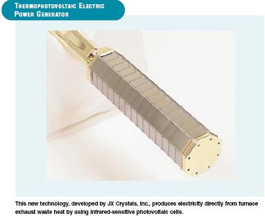
THERMOPHOTOVOLTAIC ELECTRIC POWER GENERATION USING EXHAUST HEAT


Furnaces in the glass, metalcasting, and steel industries operate at very high
temperatures and lose tremendous amounts of energy in their exhaust streams.
With the emissions-reducing shift to gas-oxy furnaces in these industries,
exhaust temperatures are climbing even higher. Waste heat from furnaces in
the glass, metalcasting, and steel industries is usually vented to the atmosphere.
In some facilities, it must be diluted with cool air to reduce its temperature prior
to venting. Until now, the venting of this waste heat has represented the loss of
a valuable resource.
A new technology adds value to this waste stream by using exhaust heat to
generate hundreds of kilowatts of electricity. This unique innovation uses new
infrared-sensitive photovoltaic cells mounted inside ceramic tubes. These tubes
are heated in the exhaust stream of an industrial process and radiate energy
inward to the photovoltaic cells to generate electricity directly from the waste
heat. The energy density in these systems is over 100 times that of solar energy,
producing over 100 times the energy of conventional photovoltaic or solar cells.

Economics and Commercial Potential
Exhaust heat offers an attractive energy alternative to the glass, metalcasting, and steel
industries. In particular, JX Crystals, Inc., has targeted the glass industry because of
an estimated 67 MW of year-round electrical generation available in this industry alone.
The technology has already attracted the partnership of a major glass-industry player
interested in demonstrating the technology on a glass furnace.
Given additional investment in the business and a market volume well over 10 MW per
year, JX Crystals, Inc., estimates the thermophotovoltaic circuit to cost approximately
$0.20 per watt. Balance of system costs are estimated to be $0.50 per watt. Assuming
a price of $1 per watt, utility rates of $0.05 per kWh, and a duty cycle of 90%, the
payback period should be less than 3 years.
This technology could save 27 billion Btu of electricity per installed unit each year. First
sales for the technology are expected by 2004. Based on 25% market penetration by
2010, annual savings could be 0.5 trillion Btu with 18 units installed, each containing 200
5-kW tubes. Market penetration of 50% by 2020 could save 1.0 trillion Btu from the
operation of 37 units by the glass industry.

Energy Storage- Shaving load peaks from the substation

Welcome to the future of bulk electricity storage. American Electric Power (AEP) installed a 1.2-MW sodium sulfur (NaS) battery and accompanying inverter (Figure 1) at the Charleston Substation of its subsidiary, Appalachian Power. The Charleston Substation was chosen to host the installation for several reasons related to economics, service reliability, and local load growth.

The main function of the system is to supply up to 7.2 MWh of electrical energy on demand for peak-shaving purposes. However, it also has a business purpose. According to AEP, the system will enable deferment of equipment upgrades to the Charleston substation for six or seven years, at which time the battery can be relocated to another substation and play similar roles there. The battery's manufacturer—NGK Insulators Ltd. of Japan—expects the battery to last for 15 years, assuming that it will be charged and discharged 4,000 to 5,000 times up to 90% of its full capacity.

In addition to using the battery system to shave demand peaks, AEP envisions employing it to accumulate and store for subsequent dispatch electrical energy generated by intermittent generating units such as wind turbines and solar cells. The name given to the system—the Distributed Energy Storage System (DESS)—implies that it will have many applications on the utility's T&D grids. "Our goal is to deploy plenty of distributed energy storage capacity on our grids over the next decade," said AEP Program Manager Ali Nourai. "We intend to have a very resilient system that can absorb customer-operated distributed generation capacity as it connects to our grid."

AEP and several other U.S. utilities are currently field-testing a variety of distributed energy storage systems. Although the Charleston battery project (which cost about $2,000/kW) was slightly more expensive than upgrading the substation's components to handle higher loads, the system is expected to deliver many intangible benefits, including invaluable and unique operating experience.

The project was partially funded by a grant from the U.S. Department of Energy's Sandia National Laboratories. Sandia will closely monitor the system's performance during the first year of service and produce detailed reports that will help other potential users of energy storage better understand the costs and benefits of using bulk storage to prop up a grid being stressed by peak demand.

AEP chose the NaS battery system for its very high power density and its operating experience in Japan. Over the past decade, NGK and the battery's co-developer, Tokyo Electric Power Co., have deployed in their home country NaS batteries totaling 150 MW of capacity.

source: powermag.com

Contactors

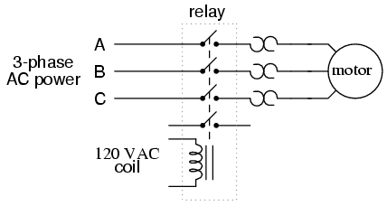
When a relay is used to switch a large amount of electrical power through its contacts, it is designated by a special name: contactor. Contactors typically have multiple contacts, and those contacts are usually (but not always) normally-open, so that power to the load is shut off when the coil is de-energized. Perhaps the most common industrial use for contactors is the control of electric motors.

The top three contacts switch the respective phases of the incoming 3-phase AC power, typically at least 480 Volts for motors 1 horsepower or greater. The lowest contact is an "auxiliary" contact which has a current rating much lower than that of the large motor power contacts, but is actuated by the same armature as the power contacts. The auxiliary contact is often used in a relay logic circuit, or for some other part of the motor control scheme, typically switching 120 Volt AC power instead of the motor voltage. One contactor may have several auxiliary contacts, either normally-open or normally-closed, if required.

The three "opposed-question-mark" shaped devices in series with each phase going to the motor are calledoverload heaters. Each "heater" element is a low-resistance strip of metal intended to heat up as the motor draws current. If the temperature of any of these heater elements reaches a critical point (equivalent to a moderate overloading of the motor), a normally-closed switch contact (not shown in the diagram) will spring open. This normally-closed contact is usually connected in series with the relay coil, so that when it opens the relay will automatically de-energize, thereby shutting off power to the motor. We will see more of this overload protection wiring in the next chapter. Overload heaters are intended to provide overcurrent protection for large electric motors, unlike circuit breakers and fuses which serve the primary purpose of providing overcurrent protection for power conductors.

Overload heater function is often misunderstood. They are not fuses; that is, it is not their function to burn open and directly break the circuit as a fuse is designed to do. Rather, overload heaters are designed to thermally mimic the heating characteristic of the particular electric motor to be protected. All motors have thermal characteristics, including the amount of heat energy generated by resistive dissipation (I2R), the thermal transfer characteristics of heat "conducted" to the cooling medium through the metal frame of the motor, the physical mass and specific heat of the materials constituting the motor, etc. These characteristics are mimicked by the overload heater on a miniature scale: when the motor heats up toward its critical temperature, so will the heater toward its critical temperature, ideally at the same rate and approach curve. Thus, the overload contact, in sensing heater temperature with a thermo-mechanical mechanism, will sense an analogue of the real motor. If the overload contact trips due to excessive heater temperature, it will be an indication that the real motor has reached its critical temperature (or, would have done so in a short while). After tripping, the heaters are supposed to cool down at the same rate and approach curve as the real motor, so that they indicate an accurate proportion of the motor's thermal condition, and will not allow power to be re-applied until the motor is truly ready for start-up again.

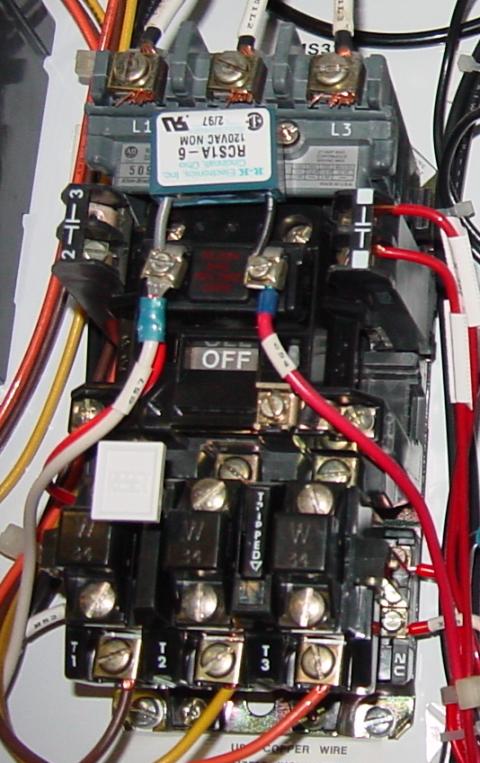
Shown here is a contactor for a three-phase electric motor, installed on a panel as part of an electrical control system at a municipal water treatment plant:

Three-phase, 480 volt AC power comes in to the three normally-open contacts at the top of the contactor via screw terminals labeled "L1," "L2," and "L3" (The "L2" terminal is hidden behind a square-shaped "snubber" circuit connected across the contactor's coil terminals). Power to the motor exits the overload heater assembly at the bottom of this device via screw terminals labeled "T1," "T2," and "T3."

The overload heater units themselves are black, square-shaped blocks with the label "W34," indicating a particular thermal response for a certain horsepower and temperature rating of electric motor. If an electric motor of differing power and/or temperature ratings were to be substituted for the one presently in service, the overload heater units would have to be replaced with units having a thermal response suitable for the new motor. The motor manufacturer can provide information on the appropriate heater units to use.

A white pushbutton located between the "T1" and "T2" line heaters serves as a way to manually re-set the normally-closed switch contact back to its normal state after having been tripped by excessive heater temperature. Wire connections to the "overload" switch contact may be seen at the lower-right of the photograph, near a label reading "NC" (normally-closed). On this particular overload unit, a small "window" with the label "Tripped" indicates a tripped condition by means of a colored flag. In this photograph, there is no "tripped" condition, and the indicator appears clear.

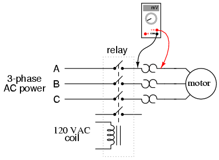
As a footnote, heater elements may be used as a crude current shunt resistor for determining whether or not a motor is drawing current when the contactor is closed. There may be times when you're working on a motor control circuit, where the contactor is located far away from the motor itself. How do you know if the motor is consuming power when the contactor coil is energized and the armature has been pulled in? If the motor's windings are burnt open, you could be sending voltage to the motor through the contactor contacts, but still have zero current, and thus no motion from the motor shaft. If a clamp-on ammeter isn't available to measure line current, you can take your multimeter and measure millivoltage across each heater element: if the current is zero, the voltage across the heater will be zero (unless the heater element itself is open, in which case the voltage across it will be large); if there is current going to the motor through that phase of the contactor, you will read a definite millivoltage across that heater:

This is an especially useful trick to use for troubleshooting 3-phase AC motors, to see if one phase winding is burnt open or disconnected, which will result in a rapidly destructive condition known as "single-phasing." If one of the lines carrying power to the motor is open, it will not have any current through it (as indicated by a 0.00 mV reading across its heater), although the other two lines will (as indicated by small amounts of voltage dropped across the respective heaters).

  • REVIEW:
  • contactor is a large relay, usually used to switch current to an electric motor or other high-power load.
  • Large electric motors can be protected from overcurrent damage through the use of overload heaters and overload contacts. If the series-connected heaters get too hot from excessive current, the normally-closed overload contact will open, de-energizing the contactor sending power to the motor.

Walking robot offers clues to human movement

A walking robot that adapts to different terrain is helping scientists understand how humans move and could one day lead to improved treatment for spinal cord and other injuries, German researchers said on Friday.
Previously, RunBot the robot's inventors said the 30-centimeter-tall machine could only walk forward on flat surfaces and would topple over when encountering a slope.
But using an infrared eye, the robot can now detect an incline in its path and adjust its gait after four or five attempts to navigate up the slope, researchers said.
The machine, which simply falls over until it learns to walk uphill, takes 3-4 stride lengths per second, a touch faster than the normal human gait of about 1.5 to 2.5 stride lengths per second.
"It is trial and error learning," said Florentin Woergoetter, a researcher at the University of Goettingen who helped design RunBot.
"It needs about four or five falls to learn this."
Woergoetter, who published his findings in the journal Computational Biology, compared the process with the way a child learns to walk. He said just like humans, RunBot leans forward slightly and uses shorter steps to navigate uphill.
A key is the robot's "brain" in this case the infrared eye connected to the control circuits—which directs the machine to change its gait when needed.

Processor lowers the cost and power thresholds for HD video

The TMS320DM355 processor is the latest addition to Texas Instruments’ DaVinci processor family. Unlike previous DaVinci devices, this processor does not include a software-programmable DSP. Rather, it couples an ARM936EJ-S core with a video-processing subsystem and MPEG-4-JPEG coprocessor that are configurable through software executing on the ARM core. The less-than-$10 processor enables HD (high-definition) video products, such as digital cameras and IP (Internet Protocol) videocameras targeting a $250 end-unit price, as well as digital-photo frames and video baby monitors targeting a $120 end-unit price. Going with a configurable hard coprocessor instead of a software-programmable DSP helps the system deliver a power consumption as low as 400 mW to support HD MPEG-4 encoding and approximately 1 mW in standby; this power consumption level allows for 80 minutes of continuous HD-video capture with two AA batteries.

The processor supports HD MPEG-4 SP encoding or decoding at 720p and 30 frames/sec and JPEG encoding or decoding at 50M pixels/sec. The processor is available in 216- or 270-MHz clock speeds; these devices support only these rates because the video subsystem and coprocessor blocks operate at the same clock rate as the processor. The video-processing subsystem is the same set of engines that all DaVinci devices feature. The processor supports the same intellectual-property and API (application-programming-interface) model as the other DaVinci devices. The processor includes production-qualified, configurable HD MPEG-4 and JPEG codecs without licensing fees or royalties. The integrated peripheral suite includes high-speed USB 2.0 OTG (On-The-Go) device and mini-host with a PHY (physical) layer, a 10-bit DAC, 32 kbytes of program/data memory, 8 kbytes of ROM, 16- and 8-kbyte instruction and data caches, and an external memory interface that supports mobile DDR/DDR2.

The DM355 is available for sampling now in a 13×13-mm, 329-pin, 0.65-mm-pitch BGA package. The 216-MHz device sells for $9.75 (50,000), and the 270-MHz device sells for $11.49 (50,000). The TMDXEVM355 evaluation module is available now for $495. It includes JPEG/MPEG 4 SP/G.711 codecs, ORCAD schematics, and MontaVista Linux with drivers for the peripherals, video-processing subsystems, and Uboot loader.

Voltage Indicators enhance safety

Near-death experiences among paper mill electricians are all too common. On this particular day, a combination circuit breaker/welding outlet failed to provide power to the welder. The maintenance electrician began to replace the outlet. Casually, his co-worker paused and said, "Better check it with a meter." The meter revealed that one phase of the circuit breaker had failed "live" leaving the outlet energized. For these guys, this near-death experience is permanently imprinted on their minds in vivid 'Technicolor' detail never to be forgotten.

Most often, hazardous voltage violently shows up resulting in loss of limbs, severe burns, or even death. On this day, a much better result: only hearts and minds were changed. At an electrical safety training seminar, a hardened, 26-year veteran electrician stood up and said, "Until today, I never knew just how dangerous electricity really is!"

Real accidents and near-death experiences coupled with the NFPA 70E compel us to find better ways to provide safety. Accurate information and rising standards stimulate innovation. Let's discuss how one paper mill used voltage indicators, otherwise known as VIs, to enhance their electrical safety program.

Simply put, electrical safety boils down to a single question: "voltage or no voltage?" Many times a day electricians ask this question and rely on a voltmeter to provide the right answer. There is no room for error.

However, wiring a VI to the primary power source provides an independent answer to the all-critical voltage question. This pushbutton-sized device is a permanently wired voltmeter that provides electricians with a full-time, visual, independent, thru-door power indication. From a safety viewpoint, voltmeters serve multiple purposes while a VI serves has a single purpose -- to indicate the presence of hazardous voltage.

In the past, this mill used neon pilot lights installed on electrical mains that provided a similar function. On the downside, a neon indicator's intensity provided limited indication of voltage levels, and this simple voltage indicator still needed fuses and replacement bulbs. After seeing the safety benefits of thru-door voltage indicators, this paper mill went a step further and built a neon indicating light assembly with access holes that electricians used to verify zero energy after opening the disconnect. They installed these on 208V lighting panels between the Hot/Neutral.

Over time, the paper mill electricians benefited from the safety value of their home-grown, thru-door voltage indicator. Looking to improve reliability, they found a single 30mm pushbutton-sized VI that overcame the limitations of the neon pilot light assembly. This 3-phase device operates at 40-750VAC/30-1000VDC, requires no fuses, uses long life LEDs, redundant circuitry, and potted construction for high reliability. In addition, it was low cost and very easy to install. The mill maintenance manager nicknamed this device the "24/7 voltmeter" and began installing a few units into those high maintenance areas of the plant. As the days went on, the mill maintenance staff began to see the benefits of this simple reliable device and started installing them throughout the plant. Let's elaborate on some of these safety benefits.

Increasingly stringent safety requirements demanded by OSHA forced this mill to add a voltage verification step to their Mechanical Lock-Out Tag-Out procedure (LOTO). Simply put, mechanics would need to have an electrician verify a zero voltage state on the load side of their circuit breaker disconnects before performing equipment maintenance. This added manpower and downtime would greatly impact the already high costs of the paper mill's scheduled shutdowns. Someone said, "It would take our entire scheduled shutdown just to shut down!" Their solution was to use a thru door VI as a substitute 'electrician' for this zero voltage checking step.

Understanding arc flash provided the foundation for our present electrical safety culture. During an electrical fault, if energy flows too long before the short circuit device opens it will vaporize copper to 5000ºF and cause a molten copper 'shrapnel' explosion. Arc flash sends ten people a day to the hospital. The causes include dropping tools on live conductors, racking out MCC buckets or circuit breakers, and voltage checking, which is a slip of a hand that puts an electrician's face very close to this potential arc flash. Also note that most arc flashes are not anyone's fault, but rather equipment failure precipitated by an electrician just doing his job.

Most 'voltage checking' arc flash incidents center on the reliable operation of the isolator. Therefore, operating the isolator and seeing a real voltage feedback from a VI provides a secondary indication that the electrical energy has been pre-verified as isolated. Moreover, for a critical failure to occur both devices would have to fail at the same time.

Therefore, we conclude that a voltage indicator applied in this application will reduce arc flash risk because a failed isolator would be discovered while the panel door is closed.

A voltage indicator, like any safety product, must have a written procedure that insures its safe and consistent application (even cars equipped with the latest safety gadgets still need traffic laws to be safe!). The first step in applying a VI requires the electrician to verify its proper operation. Are the LEDs flashing correctly for the power system? After opening the isolator, visually inspect the VI to verify that all the LEDs cease to flash. Once the voltage returns, either planned or accidentally, re-verify proper operation of the VI.

In an eight step LOTO procedure, the electrician's voltmeter stays in his tool belt until step 6.5.(2) Think about the safety benefits when voltage information is provided to the electrician before, after, and during their entire LOTO procedure. This discussion is not complete without mentioning the first law of electrical safety: validate your voltage tester before working directly on electrical conductors.(3) In other words, test the tester, test for zero voltage, and then test the tester again (nicknamed the 'live-dead-live' procedure. The 'test the tester' principle applies to any device, whether it is a $6.95 outlet tester or high end Fluke multimeter!

In order to fully validate a VI with the 'live-dead-live' procedure, the 3-phase power must be re-applied to the device. In most cases this is impractical. Therefore, voltmeters and VI's are on the same electrical safety team, yet both provide unique safety functions.

Instantaneous and invisible electrical energy poses a unique threat to maintenance people. When electricity shows up for an accident it kills 5% of its victims. The good ol' time tested voltmeter still remains as the 'guard dog' between maintenance people and voltage. Both the voltmeter and the voltage indicator are on the same team with their own unique safety benefits; however, would our near-death experience have happened if a '24/7 voltmeter' had been installed?

From: 
automation.com

Building A Lighting Harnessing Power Plant


How hard would it be to build a power plant that harnesses the electricity generated by lightning? Then, store the electricity and use it on-demand on the electric grid? 

This concept is perhaps not as impractical as it once was. The main limiting factor of implementing a lightning capturing scheme such as this was the inability to be able to store large amounts of electricity for later use. However, new Utility Scale Battery technology or other energy storage technologies such as Flywheels or Capacitors could be used to store the electricity captured from lightning in massive quanties, for later grid use.

Obviously, a lightning capturing power plant would only be practical in regions with frequent thunderstorms, such as Florida.

How hard would it be to build an array of lighting rods to capture periodic thunderstorm electricity? The biggest hurdle would really be creating power plant infrastructure that could survive the harsh surges created by lightning strikes, but even that seems possible with current technology and materials. Electrical and building design engineers could come up with an innovative way to make it work. Specially designed buffer/insulation and transformer materials could be used to safely capture and harness the massive amounts of electricity generated during a lighting strike, and transfer it to large storage device for later use.

AMD Micro Processors, History


Am2900 series (1975)

* Am2901 4-bit-slice ALU (1975)
* Am2902 Look-Ahead Carry Generator
* Am2903 4-bit-slice ALU, with hardware multiply
* Am2904 Status and Shift Control Unit
* Am2905 Bus Transceiver
* Am2906 Bus Transceiver with Parity
* Am2907 Bus Transceiver with Parity
* Am2908 Bus Transceiver with Parity
* Am2909 4-bit-slice address sequencer
* Am2910 12-bit address sequencer
* Am2911 4-bit-slice address sequencer
* Am2912 Bus Transceiver
* Am2913 Priority Interrupt Expander
* Am2914 Priority Interrupt Controller

29000 (29K) (1987–95)

* AMD 29000 (aka 29K) (1987)
* AMD 29027 FPU
* AMD 29030
* AMD 29050 with on-chip FPU (1990)
* AMD 292xx embedded processor

x86 architecture processors

2nd source (1979–91)

(second-sourced x86 processors produced under contract with Intel)

* 8086
* 8088
* Am286 (2nd-sourced 80286, so not a proper Amx86 member)

Amx86 series (1991–95)

* Am386 (1991)
* Am486 (1993)
* Am5x86 (a 486-class µP) (1995)

K5 series (1995)

* AMD K5 (SSA5/5k86)

K6 series (1997–2001)

* AMD K6 (NX686/Little Foot) (1997)
* AMD K6-2 (Chompers/CXT)
o AMD K6-2-P (Mobile K6-2)
* AMD K6-III (Sharptooth)
o AMD K6-III-P
* AMD K6-2+
* AMD K6-III+

K7 series (1999–2005)

* Athlon (Slot A) (Argon,Pluto/Orion,Thunderbird) (1999)
* Athlon (Socket A) (Thunderbird) (2000)
* Duron (Spitfire,Morgan,Applebred) (2000)
* Athlon MP (Palomino,Thoroughbred,Barton,Thorton) (2001)
* Mobile Athlon 4 (Corvette/Mobile Palomino) (2001)
* Athlon XP (Palomino,Thoroughbred (A/B),Barton,Thorton) (2001)
* Mobile Athlon XP (Mobile Palomino) (2002)
* Mobile Duron (Camaro/Mobile Morgan) (2002)
* Sempron (Thoroughbred,Thorton,Barton) (2004)
* Mobile Sempron

K8 series (2003–)

Families: Opteron, Athlon 64, Sempron, Turion 64, Athlon 64 X2, Turion 64 X2

* Opteron (SledgeHammer) (2003)
* Athlon 64 FX (SledgeHammer) (2003)
* Athlon 64 (ClawHammer/Newcastle) (2003)
* Mobile Athlon 64 (Newcastle) (2004)
* Athlon XP-M (Dublin) (2004) Note: AMD64 disabled
* Sempron (Paris) (2004) Note: AMD64 disabled
* Athlon 64 (Winchester) (2004)
* Turion 64 (Lancaster) (2005)
* Athlon 64 FX (San Diego) (1st half 2005)
* Athlon 64 (San Diego/Venice) (1st half 2005)
* Sempron (Palermo) (1st half 2005)
* Athlon 64 X2 (Manchester) (1st half 2005)
* Athlon 64 X2 (Toledo) (1st half 2005)
* Athlon 64 FX (Toledo) (2nd half 2005)
* Turion 64 X2 (Taylor) (1st half 2006)
* Athlon 64 X2 (Windsor) (1st half 2006)
* Athlon 64 FX (Windsor) (1st half 2006)
* Athlon 64 X2 (Brisbane) (2nd half 2006)
* Athlon 64 (Orleans) (2nd half 2006)
* Sempron (Manila) (1st half 2006)
* Opteron (Santa Rosa)
* Opteron (Santa Ana)
* Mobile Sempron

K9 series

At one time K9 was the internal codename for the dual-core AMD64 processors as the brand Athlon 64 X2,[1][2] however AMD has distanced itself from the old K series naming convention, and now seeks to talk about a portfolio of products, tailored to different markets.[3]

K10 series
This article contains information about scheduled or expected future computer chips.
It may contain preliminary or speculative information, and may not reflect the final specification of the product. 

* Opteron (Barcelona) (10 September 2007)
* Phenom FX (Agena FX) (Q1 2008)
* Phenom 9-series (Agena) (Q4 2007)
* Phenom 8-series (Toliman) (H1 2008)
* Athlon 6-series (Kuma) (Q1 2008)
* Athlon 4-series (Kuma) (2008)
* Athlon X2 (Rana) (Q4 2007)
* Sempron (Spica)
* Opteron (Budapest)
* Opteron (Shanghai)
* Opteron (Cadiz)
* Opteron (Zamora)
* Opteron (Montreal)

Researchers demonstrate ‘avalanche effect’ in solar cells


Proof that the ‘avalanche effect’ by electrons occurs in specific, very small semi conducting crystals could pave the way for cheap high-output solar cells.

Researchers at TU Delft and the FOM Foundation for Fundamental Research on Matter have discovered this phenomenon.

Solar cells provide opportunities for future large-scale electricity generation. However, there are currently significant limitations, such as the relatively low output of most solar cells (typically 15%) and high manufacturing costs.

One possible improvement could develop from a solar cell made of semiconducting nanocrystals which could lead to theoretical maximum output of 44%.

In conventional solar cells, one photon can release precisely one electron. The creation of these free electrons ensures that the solar cell works and can provide power.

The more electrons released, the higher the output of the solar cell.

In some semiconducting nanocrystals, however, one photon can release two or three electrons, hence the term 'avalanche effect'.

The avalanche effect was first measured by researchers at the Los Alamos National Laboratories in 2004. Since then, the scientific world has raised doubts about the value of these measurements. Does the avalanche effect really exist or not?

Within the Joint Solar Programme TU Delft’s Prof Laurens Siebbeles has now demonstrated that the avalanche effect does indeed occur in lead selenide (PbSe) nanocrystals.

It has been established, however, that the effect in this material is smaller than previously assumed. Siebbeles claims his results are more reliable than those of other scientists due to more careful and more detailed measurement using ultra-fast laser methods.

Siebbeles believes that this research paves the way for further unravelling the secrets of the avalanche effect.
Source: electroline.com

Fibre replaces substation copper

GE Digital Energy says its Multilin HardFiber System eliminates the need for thousands of copper wires in a substation and replaces them with a few fibre-optic cables.
By eliminating the need to install and maintain the copper wires, used for signalling and monitoring in electrical substations, utilities can save up to 50% of protection and control installation and maintenance costs, while at the same time increasing worker safety and power system reliability.
The system, based on IEC 61850, is made up of four key elements: the brick, the cross connect panel, the rugged outdoor fibre cables and the universal relay IEC 61850 process card.
The system's single, pre-terminated fibre-optic connections reduce the multitude of copper wires that need to be pulled, spliced and terminated.
It provides an identical interface to all primary system equipment, eliminating custom designs.
Source

Nanotechnology improves battery life

Researchers at the Shenyang National Laboratory for Materials Science in China have been investigating how to improve the kind of rechargeable batteries that are used in mobile phones, MP3 players, personal digital assistants and laptop computers.

They found that after 20 cycles of the semi-cell experiments, the sugar-coated Si-CNT composite material achieved a discharge capacity of 727 mAh per g. In contrast, the charge capacity of the simple sugar-coated particles had dropped to 363 mAh per g.

Hui-Ming Cheng and colleagues have turned to carbon nanotubes (CNTs) to help them use silicon (Si) as the battery anode but avoid the material's usual problem of large volume change during alloying and de-alloying that can lead to faster capacity loss.

Li-Ion batteries suffer from degradation, especially when they get too hot or too cold, and eventually lose the capacity to be fully recharged. The problem of the slow degradation of Li-Ion batteries is usually due to the formation of a solid electrolyte interphase film that increases the batteries' internal resistance and prevents a full recharge.

The researchers grew carbon nanotubes on the surface of tiny particles of silicon using a technique known as chemical vapour deposition, in which a carbon-containing vapour decomposes and then condenses on the surface of the silicon particles forming the nanoscopic tubes.

They then coated these particles with carbon released from sugar at a high temperature in a vacuum. A separate batch of silicon particles produced using sugar but without the CNTs was also prepared.

With the Si-CNT anode material to hand, the team then investigated how well it functioned in a prototype Li-Ion battery and compared the results with the material formed from sugar-coated silicon particles.

The growth of carbon nanotubes on silicon suppresses the structure destruction of the composite during charge cycling, resulting in the improvement of cyclability, according to the researchers.

Window collects light and illuminates room !!

Imagine windows that not only provide a clear view and illuminate rooms, but also efficiently help power the building. MIT engineers report a new approach to harnessing the sun's energy that could allow just that.

The work involves creating a ‘solar concentrator’.

"Light is collected over a large area [like a window] and gathered or concentrated, at the edges," explains Marc A Baldo, leader of the work and the Esther and Harold E Edgerton Career Development Associate Professor of Electrical Engineering.

As a result, rather than covering a roof with solar cells, the cells only need to be around the edges of a flat glass panel. In addition, the focused light increases the electrical power obtained from each solar cell "by a factor of over 40," Baldo says.

Because the system is simple to manufacture, the team believes that it could be implemented within three years — even added onto existing solar-panel systems to increase their efficiency by 50%.

In addition to Baldo, the researchers involved are Michael Currie, Jon Mapel and Timothy Heidel, all graduate students in the Department of Electrical Engineering and Computer Science, and Shalom Goffri, a postdoctoral associate in MIT's Research Laboratory of Electronics.

"Professor Baldo's project uses design to achieve superior solar conversion without optical tracking," says Dr Aravinda Kini, program manager in the Office of Basic Energy Sciences in the US Department of Energy's Office of Science, a sponsor of the work.

"This accomplishment demonstrates the importance of innovative basic research in bringing about advances in solar energy use."

Solar concentrators in use today "track the sun to generate high optical intensities, often by using large mobile mirrors that are expensive to deploy and maintain," Baldo says. Solar cells at the focal point of the mirrors must be cooled and the entire assembly wastes space around the perimeter to avoid shadowing neighbouring concentrators.

The concentrator is a mixture of two or more dyes, painted onto a pane of glass or plastic. The dyes work together to absorb light across a range of wavelengths, which is then re-emitted at a different wavelength and transported across the pane to waiting solar cells at the edges.

In the 1970s, similar solar concentrators were developed by impregnating dyes in plastic. But the idea was abandoned because, among other things, not enough of the collected light could reach the edges of the concentrator as much of it was lost en route.

The MIT engineers, experts in optical techniques developed for lasers and organic light-emitting diodes, realised that perhaps those same advances could be applied to solar concentrators. The result? A mixture of dyes in specific ratios, applied only to the surface of the glass, that allows some level of control over light absorption and emission.

"We made it so the light can travel a much longer distance," Mapel said.

"We were able to substantially reduce light transport losses, resulting in a tenfold increase in the amount of power converted by the solar cells."

Source: www.electroline.com

Electricity from a thin film

Researchers at The Fraunhofer Institute for Solar Energy Systems ISE in Freiburg, Germany are working towards the industrial mass production of organic solar cells.

These cells can be laid onto thin films, which make them cheap to produce and established printing technologies could be used for future production.

However, to achieve suitable solar cell architecture, coating materials and substrates have to be developed.

”This method permits a high throughput, so the greatest cost is that of materials,” said Michael Niggemann, a researcher at ISE.

Organic solar cells are not efficient enough to compete with classic silicon cells yet but because they are flexible they can open up new fields of application, for example, plastic solar cells could supply the power for small mobile devices such as MP3 players or electronic passes.

Another possibility would be to combine solar cells, sensors and electronic circuits on a small strip of plastic to form a self-sufficient power microsystem.

Until now, the front electrode has usually been made of expensive indium tin oxide because this material is transparent. But the Fraunhofer team has found an alternative by interconnecting a poorly conductive transparent polymer electrode with a highly conductive metal layer on the rear side of the solar cell.

This connection is through numerous tiny holes in the solar cell .This has the advantage that a low-priced material can be used.

Source: www.electroline.com.au

Squeezing More Synthetic Fuel From Abundant Supplies Of Coal


Scientists in Italy are reporting that a new process could eliminate key obstacles to expanded use of coal gasification to transform that abundant domestic energy resource into synthetic liquid fuels for cars and trucks. 
In the study, Maria Sudiro and colleagues note that coal is the only conventional energy source with the potential for meeting global energy demands in the near future. World coal reserves, they note, are 25 percent greater than crude oil and the United States alone has enough coal to supply its own energy needs for centuries. However, existing processes for converting coal into much-needed liquid fuels are uneconomical and release too much carbon dioxide, a greenhouse gas, and other air pollutants.
Based on laboratory simulations and comparisons with conventional coal gasification, their system was 70 percent more energy efficient, yielded 40 percent more fuel and released 32 per cent less carbon dioxide. "The new process configuration can represent a valuable alternative route to obtain syngas both for electric power generation and for synthetic fuel production," the report states.
Source: Sciencedaily.com

New Small-scale Generator Produces Alternating Current By Stretching Zinc Oxide Wires

The new "flexible charge pump" generator is the fourth generation of devices designed to produce electrical current by using the piezoelectric properties of zinc oxide structures to harvest mechanical energy from the environment. Its development was scheduled to be reported November 9, 2008 in the advance online publication of the journal Nature Nanotechnology.
"The flexible charge pump offers yet another option for converting mechanical energy into electrical energy," said Zhong Lin Wang, Regent's professor and director of the Center for Nanostructure Characterization at the Georgia Institute of Technology. "This adds to our family of very small-scale generators able to power devices used in medical sensing, environmental monitoring, defense technology and personal electronics."
The new generator can produce an oscillating output voltage of up to 45 millivolts, converting nearly seven percent of the mechanical energy applied directly to the zinc oxide wires into electricity. The research has been supported by the U.S. Department of Energy, the National Science Foundation, the Air Force Office of Scientific Research and the Emory-Georgia Tech Center for Cancer Nanotechnology Excellence.
Earlier nanowire nanogenerators and microfiber nanogenerators developed by Wang and his research team depended on intermittent contact between vertically-grown zinc oxide nanowires and an electrode, or the mechanical scrubbing of nanowire-covered fibers. These devices were difficult to construct, and the mechanical contact required caused wear that limited how long they could operate. And because zinc oxide is soluble in water, they had to be protected from moisture.
"Our new flexible charge pump resolves several key issues with our previous generators," Wang said. "The new design would be more robust, eliminating the problem of moisture infiltration and the wearing of the structures. From a practical standpoint, this would be a major advantage."
To boost the current produced, arrays of the flexible charge pumps could be constructed and connected in series. Multiple layers of the generators could also be built up, forming modules that could then be embedded into clothing, flags, building decorations, shoes – or even implanted in the body to power blood pressure or other sensors.
When the modules are mechanically stretched and then released, because of the piezoelectric properties, the zinc oxide material generates a piezoelectric potential that alternately builds up and then is released. A Schottky barrier controls the alternating flow of electrons, and the piezoelectric potential is the driving force of the charge pump.
"The electrons flow in and out, just like AC current," Wang explained. "The alternating flow of electrons is the power output process."
Constructed with zinc oxide piezoelectric fine wires with diameters of three to five microns and lengths of 200 to 300 microns, the new generator no longer depends on nanometer-scale structures. The larger size was chosen for easier fabrication, but Wang said the principles could be scaled down to the nanometer scale.
"Nanoscale materials are not required for this to work," he said. "Larger fibers work better and are easier to work with to fabricate devices. But the same principle would apply at the nanometer scale."
The wires are grown using a physical vapor deposition method at approximately 600 degrees Celsius. Using an optical microscope, the wires are then bonded onto a polyimide film and silver paste applied at both ends to serve as electrodes. The wires and electrodes were then encased in polyimide to protect them from wear and environmental degradation.
To measure the electric energy generated, the researchers subjected the substrate and attached zinc oxide wires to periodic mechanical bending created by a motor-driven mechanical arm. The bending induced tensile strain which created a piezoelectric potential field along the laterally-packaged wires. That, in turn, drove a flow of electrons into an external circuit, creating the alternating charge and discharge cycle – and corresponding current flow.
Increasing the strain rate increased the magnitude of the output electricity, both in voltage and current. Wang believes the frequency of the current is limited only by the mechanical properties of the polyimide substrate.
The researchers conducted a number of tests to verify that the current measured was produced by the generator – and not an external measurement artifact. Using the same experimental setup, they stretched carbon fibers and Kevlar fibers coated with polycrystalline zinc oxide, and did not observe current flow. The research team also developed two criteria and eight tests for ruling out experimental artifacts, Wang noted.
In addition to Wang, the research team included Rusen Yang and Yong Qin from Georgia Tech and Liming Dai of the Department of Chemical and Materials Engineering at the University of Dayton.
For the future, Wang sees the family of small-scale generators enabling development of a new class self-powered wireless sensing systems. The devices could gather information, store it and transmit the data – all without an external power source.
"Self-powered nanotechnology could be the basis for a new industry," he said. "That's really the only way to build independent systems."